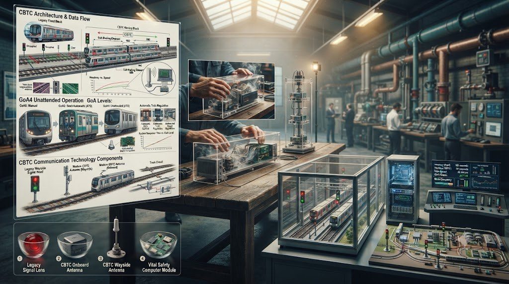
Metropolitan mass transit networks worldwide face soaring passenger ridership demands that cannot be accommodated simply by boring more tunnels or expanding station footprints. The primary mechanism for maximizing urban passenger throughput is Communications-Based Train Control (CBTC), a high-performance continuous automatic train control system that leverages bidirectional wireless communications, precise onboard odometry, and centralized wayside computer interlocking to operate trains at Grades of Automation (GoA) reaching fully unattended driverless operation (GoA4).
Governed by IEEE 1474 standards, CBTC replaces traditional fixed track-circuit block signaling with high-resolution digital telemetry. By continuously transmitting precise train location, velocity, and health data to wayside Zone Controllers, CBTC enables trains to operate safely under dynamic moving-block headways as tight as 75 to 90 seconds while eliminating thousands of failure-prone trackside optical signal masts and relay enclosures.
🚂 IEC 62290 Grades of Automation (GoA) Hierarchy
Railway automation is internationally standardized across four distinct levels: GoA1 represents manual operation with Automatic Train Protection (ATP); GoA2 involves semi-automatic train operation (ATO) where the train accelerates and brakes automatically between stations while a human driver closes doors and handles emergencies; GoA3 features driverless operation with an onboard roaming attendant; and GoA4 designates completely unattended train operation (UTO) where no human crew is present aboard the revenue train.
System Architecture: ATO, ATP, ATS, and Data Communication Systems
A full CBTC operational deployment is structured across four tightly integrated technological subsystems working in microsecond synchronization:
| Subsystem Abbreviation | Full Subsystem Title | Safety Classification | Primary Core Functions |
|---|---|---|---|
| ATP | Automatic Train Protection | Vital / SIL-4 Certified | Continuous overspeed protection, rollback prevention, door interlock safety, and dynamic emergency braking enforcement. |
| ATO | Automatic Train Operation | Non-Vital / SIL-2 | Automated traction and service brake regulation, station platform precision stopping (±15 cm), and scheduled speed profiling. |
| ATS | Automatic Train Supervision | Non-Vital Supervisory | Centralized dispatching, automated timetable tracking, route reservation, headway regulation, and fleet diversion dispatch. |
| DCS | Data Communication System | High-Availability Wireless | Redundant bidirectional radio links (WLAN 5.8 GHz, LTE-R, or 5G-R) transmitting train-to-wayside telemetry packets (< 150 ms latency). |
Precision Odometry, Doppler Radar, and Balise Transponders
To compute its real-time position within millimeter tolerances without relying on line-of-sight satellite GPS (which is entirely blocked in underground subway tunnels), a GoA4 automated train relies on an onboard multi-sensor odometry fusion cluster. High-resolution axle shaft optical encoders measure wheel rotational increments, while non-contact microwave Doppler radar sensors directed at the trackbed calculate true ground velocity independent of wheel slip or slide conditions.
Accumulated odometric drift errors are continuously recalibrated whenever the vehicle passes over passive radio-frequency transponders—termed electronic balises or eurobalises—permanently bolted to the track ties. The balise transmits an invariant geographical coordinate to the train’s undercarriage antenna, resetting position drift to absolute zero.
Platform Screen Doors (PSD) and Passenger Safety Interlocking
In GoA4 unattended automated metros, safety interfaces at station platforms are paramount. Platform Screen Doors (PSD) physically segregate waiting crowds on the platform edge from the electrified trackway and moving rolling stock. The PSD control system is vital-interlocked with the wayside CBTC Zone Controller: train traction power cannot be applied until all train passenger doors and platform screen doors are electronically locked, proven closed, and laser curtain obstacle detection systems verify that no passenger or luggage is trapped between the two door planes.
DCS Radio Frequency Engineering: Leaky Feeder Coax vs. LTE-R / 5G-R
The uninterrupted operational integrity of a GoA4 driverless metro relies entirely on the continuous availability of the Data Communication System (DCS) wireless radio link. Because underground subway tunnels, sharp curves, and concrete station caverns create severe multipath fading, shadow zones, and RF signal attenuation, transit radio engineers deploy specialized physical transmission media:
- Leaky Feeder Coaxial Cables: Slotted coaxial cables suspended along tunnel walls that act as continuous, distributed RF antennas emitting uniform low-power electromagnetic signals along every meter of track, completely eliminating tunnel dead zones.
- Free-Propagation Directive Antennas: High-gain directional horn or panel antennas mounted at tunnel portals and station throats transmitting over IEEE 802.11 Wi-Fi (5.8 GHz) or dedicated LTE-R (Railway LTE 450/800 MHz) frequency bands.
- Dual Redundant Radio Networks: GoA4 systems deploy two physically and logically separate wireless radio networks (Network A and Network B) operating on distinct frequencies. Train-borne transceivers transmit packets across both networks simultaneously; if an access point drops or encounters local interference, the wayside controller continues operating seamlessly on the redundant stream without packet loss.
🚂 GoA4 Sleep-Awake Automation and Depoting Workflows
A truly unattended GoA4 metro system automates not merely mainline running, but the entire operational depot lifecycle. Every morning at 4:30 AM, the central Automatic Train Supervision (ATS) server sends digital wake-up commands over wayside Wi-Fi. Driverless trains in the storage depot power on their auxiliary inverters, perform automated pneumatic brake leakage self-tests, verify traction motor health, test platform door interlocks, and autonomously drive themselves out of the maintenance depot onto the mainline revenue tracks in precise timetable synchronization.
Precision Station Stopping Profiles and Creep Control
In GoA4 driverless operations, the Automatic Train Operation (ATO) software must align train passenger doors with stationary Platform Screen Doors with millimeter precision—typically requiring a stopping accuracy within ±150 mm (±6 inches) along an 8-car, 160-meter trainset. To achieve this repeatability under varying passenger car loads (empty vs. crush load) and fluctuating railhead adhesion (dry vs. wet condensation), the ATO software executes continuous multi-phase deceleration profiling:
- High-Speed Deceleration Phase: Utilizes full regenerative service braking at 1.0 to 1.2 m/s2 down to 10 km/h.
- Final Creep & Align Phase: Transitions to a low-speed creep approach (typically 0.1 to 0.2 m/s) guided by ultra-fine optical or radar distance sensors detecting trackside precision positioning balises.
- Holding Brake Application: Once zero speed is verified, electro-pneumatic friction brakes clamp the wheelsets with high holding pressure to prevent rollback while doors cycle.
Wayside Zone Controllers and Object Controller Architecture
The computational backbone of a CBTC installation is distributed across wayside Zone Controllers (ZC) housed in secure equipment rooms along the corridor. Each ZC manages a designated geographic territory (typically 5 to 10 km). It receives continuous position reports from all trains within its zone, interfaces with computer-based switch interlockings to verify turnout point lock states, and computes individualized Movement Authorities for every train. Failures are mitigated through 2oo3 triple voting microprocessors, ensuring uninterrupted revenue service even in the presence of single-point hardware faults.
Signaling Safety Standards, CENELEC SIL-4, and Commissioning
Railway signaling and automatic train control systems represent vital life-safety infrastructure governed by uncompromising international safety regulations. In Europe and worldwide, signaling software and electronic hardware are governed by the European Committee for Electrotechnical Standardization (CENELEC) standards: EN 50126 (RAMS: Reliability, Availability, Maintainability, and Safety), EN 50128 (Software for Railway Control and Protection), and EN 50129 (Safety-Related Electronic Systems for Signaling). These standards mandate Safety Integrity Level 4 (SIL-4) compliance—the highest attainable functional safety classification—requiring a probability of catastrophic failure with dangerous undetected potential of less than 10-9 failures per operating hour.
Commissioning an automated train control or signaling network follows an exhaustive safety assurance process:
- Hardware-in-the-Loop (HIL) Factory Interlocking Testing: Before trackside deployment, all computerized interlocking software, switch controls, and signal route logic are validated in laboratory simulation rigs running thousands of automated boundary test cases, proving that conflicting train routes can never be granted under any logic failure mode.
- Wayside Radio Coverage and Latency Surveys: Dedicated telecom measurement vehicles survey the entire rail corridor, verifying that train-to-wayside radio field strength (GSM-R, LTE-R, or Wi-Fi) maintains zero packet dropouts and latency below 150 ms across tunnel caverns, deep cuttings, and urban viaducts.
- Shadow-Running Validation: New automated signaling systems operate in the background (‘shadow mode’) aboard revenue trains for thousands of operational hours without controlling the brakes, comparing computerized movement authorities against existing signaling to verify 100% operational reliability.
Signaling System Maintenance Lifecycle and Diagnostics
To prevent signal failures that cause network-wide gridlock, signaling systems rely on continuous condition monitoring and structured maintenance tiers:
| Maintenance Interval | Inspection Classification | Signaling Subsystem Procedures |
|---|---|---|
| Daily Automated Telemetry | Continuous Interlocking Logging | Automatic event-log analysis of switch throw times, track circuit audio frequency voltages, axle counter coil pulse amplitudes. |
| Monthly Preventative Check | Trackside Sensor & Balise Audit | Physical cleaning and alignment check of inductive wheel sensors, Eurobalises, LEU enclosure gaskets, and fiber optic data splices. |
| Quarterly Relay & Switch Test | Point Machine Throw-Force Testing | Measurement of switch point machine hydraulic/electric operating current, throw force (< 6 kN), and mechanical lock rod clearances. |
| Annual Recertification | SIL-4 Power & Insulation Testing | Ground fault insulation resistance testing on vital signaling cables, backup battery UPS discharge load bank tests, and software checksum audits. |
Technical Frequently Asked Questions (FAQ)
What is the fundamental difference between fixed block and moving block signaling?
Fixed block signaling divides the track into permanently defined physical sections (blocks) demarcated by optical signals, track circuits, or axle counters. Only one train is allowed inside a block at any time, requiring following trains to maintain large buffer distances based on worst-case braking calculations. Moving block signaling (such as CBTC or ETCS Level 3) eliminates physical blocks entirely. Using real-time bidirectional wireless radio and onboard odometry, the system calculates a dynamic safety envelope around each train that travels along the track with the train. This allows trains to follow each other safely at distances based on actual real-time braking performance, slashing headways to under 90 seconds.
How does CENELEC SIL-4 certification guarantee fail-safe operation?
Safety Integrity Level 4 (SIL-4) requires that any conceivable electronic or software fault must always lead to a known safe state (fail-safe). For railway signaling, the safe state is always ‘Stop’ (Red aspect, traction power cut, brakes applied). SIL-4 is achieved using hardware redundancy—such as 2-out-of-2 (2oo2) checked processors that automatically shut down if calculations disagree, or 2-out-of-3 (2oo3) triple modular redundancy where voting algorithms outvote a malfunctioning microprocessor—combined with mathematically proven, independently audited software routines.
Why are axle counters replacing track circuits on modern railway lines?
Audio Frequency Track Circuits require electric current to flow through the running rails, making them vulnerable to water pooling, chemical contamination, rusty rail surfaces, and ballast electrical resistance drops that cause false signal failures. Furthermore, they require maintenance-intensive Insulated Rail Joints (IRJs) every few hundred meters. Modern inductive axle counters clamp to the rail web, detect wheel flanges magnetically, and are completely immune to wet ballast, rust, or flooding. They eliminate insulated rail joints entirely, allowing continuous welded rail with vastly lower maintenance expenditure.
What is an electronic balise and how does it transmit data to a train?
An electronic balise (such as a Eurobalise) is a ruggedized passive transponder mounted in the center of the track ties. It contains no internal batteries or power cords. When a train passes overhead, the antenna of the train’s Balise Transmission Module (BTM) emits a 27.095 MHz electromagnetic field. This field inductively energizes the balise via magnetic resonance, prompting it to immediately transmit an encoded digital telegram packet at 4.23 MHz carrying vital geographic position coordinates, track speed limits, and upcoming gradient profiles to the train’s cab computer.
Next-Generation 5G-R (5G for Railways) and Edge Cloud Interlockings
As metropolitan subway networks scale up passenger capacity to handle 40 trains per hour on a single trunk line, legacy Wi-Fi and LTE-R communications links are encountering bandwidth and latency bottlenecks. Transit agencies are actively migrating CBTC networks to dedicated 5G-R (5G for Railways) cellular networks operating under Ultra-Reliable Low-Latency Communication (URLLC) slices. 5G-R guarantees packet delivery latencies under 5 milliseconds with 99.999% telecommunication availability, even inside high-velocity tunnels.
Simultaneously, signaling manufacturers are virtualizing wayside hardware through Cloud-Based Interlockings and Virtual Zone Controllers. Instead of maintaining proprietary computer hardware in trackside relay rooms every few kilometers, signaling logic runs on commercial off-the-shelf (COTS) redundant server clusters in centralized data centers. Software-defined safety containers manage wayside switch machines and platform screen doors over high-speed redundant fiber loops, slashing trackside maintenance footprints by up to 70%.
AI-Powered Obstacle Detection and Flange Lubrication Telemetry
To enhance safety in GoA4 unattended automated metros, trains are being equipped with forward-facing multi-spectral obstacle detection pods mounted beneath the aerodynamic nose. Combining long-range stereoscopic machine vision cameras, pulsed flash LIDAR, and millimeter-wave radar, the onboard AI computer detects track obstructions—such as dropped passenger luggage, fallen debris, or unauthorized trespassers—at distances up to 300 meters in pitch-black tunnels. The system automatically triggers emergency braking long before a human driver could visually identify the hazard.