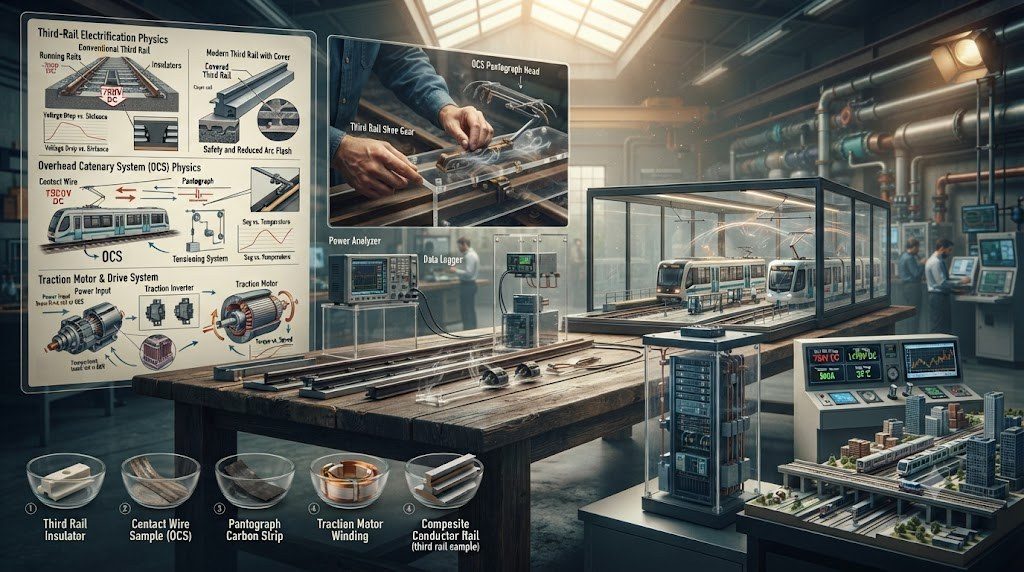
Urban rail transit networks—encompassing underground heavy metro subways, automated rapid transit lines, and surface Light Rail Transit (LRT) systems—constitute the energetic circulatory system of global megacities. A central architectural decision that defines the capital budget, civil tunnel clearances, visual landscape aesthetics, and operational safety of an urban transit system is the selection of its traction power electrification methodology: specifically, Overhead Catenary Systems (OCS) versus Bottom-Contact or Top-Contact Third-Rail Systems.
Each electrification paradigm imposes distinct electromechanical trade-offs between operating voltage, current carrying capacity, substations spacing, passenger safety barriers, and maintenance access schedules across dense metropolitan rights-of-way.
🚂 The Voltage and Current Density Trade-Off
Ohm’s Law (P = V x I) dictates that for a given traction power demand (e.g., 3 MW during rapid acceleration), doubling the electrification voltage cuts the required operating current in half. Lower current reduces resistive heat dissipation losses (I^2 x R) in conductors and allows traction substations to be spaced much further apart. Metro systems choose between 750V DC (compact, safe clearances) and 1,500V DC or 25 kV AC (higher power, larger civil envelope).
Third-Rail Electrification vs. Overhead Catenary Systems (OCS)
Urban transit authorities evaluate the engineering merits of third-rail and overhead catenary systems against strict civil and geographic criteria:
| Engineering Feature | Third-Rail Electrification (DC) | Overhead Catenary System (OCS / OLE) | Operational Engineering Impact |
|---|---|---|---|
| Operating Voltage Range | Typically 600V to 750V DC (max 1,200V DC). | 1,500V DC (metro) or 25 kV AC (commuter/high-speed). | Higher voltage allows longer substation spacing (up to 30-50 km for AC vs 2-3 km for DC). |
| Tunnel Clearance Profile | Ultra-compact: fits inside narrow bored circular tunnels. | Demands high ceiling clearances (minimum 4.5m – 5.5m). | Third rail slashes tunnel boring excavation cross-section volume by 20% to 30%. |
| Contact Geometry Type | Top-contact, bottom-contact, or side-contact steel rail. | Overhead contact wire with pantograph carbon strips. | Bottom-contact third rail (with top shroud) shields against snow, ice, and human contact. |
| Grade-Crossing Viability | Strictly prohibited across public street grade crossings. | Safe across street intersections; wires suspended overhead. | LRT systems running down street medians must utilize overhead catenary systems. |
| Current Carrying Capacity | High: heavy steel/aluminum contact rails carry up to 6,000A. | Limited by copper contact wire cross-section (100 – 150 mm^2). | Third rail easily supports intense multi-megawatt low-voltage DC starting acceleration. |
Light Rail Transit (LRT) Street-Running Integration and Cat-Free Catenary
Modern Light Rail Transit (LRT) systems operate in mixed urban street running, pedestrianized civic avenues, and segregated rights-of-way. In historic city centers where overhead copper wires and steel support poles are architecturally unacceptable, transit authorities deploy innovative catenary-free electrification:
- Segmented Ground-Level Power Supply (APS): Embedded flush between running rails is a central segmented third rail. The rail sections are electrically dead until an approaching tram with specialized radio beacons passes overhead, energizing only the 8-meter segment directly beneath the vehicle body.
- Onboard Rapid-Charge Supercapacitors: Trams carry rooftop lithium-ion capacitors that recharge in 20 to 30 seconds via high-power pantograph overhead chargers installed exclusively at passenger stations during regular dwell times.
Regenerative Braking and Wayside Energy Storage Systems (WESS)
Urban metro and LRT vehicles accelerate and brake repeatedly at station stops every 600 to 1,200 meters. During deceleration, traction motors operate as generators, converting vehicle kinetic energy back into electrical current. To harvest this vast energy resource rather than wasting it as heat in braking resistors, modern transit systems deploy Wayside Energy Storage Systems (WESS) containing flywheel accumulators or megawatt-scale lithium-titanate batteries that capture braking energy and instantly inject it back into accelerating trains, cutting total network electrical consumption by 18% to 30%.
DC Traction Voltage Selection: 750V vs. 1,500V Systems Engineering
In the systems engineering of urban rail transit, the choice between 750V DC and 1,500V DC traction electrification establishes fundamental civil and electromechanical constraints across the network. The physics of electrical power transmission dictates that current is inversely proportional to voltage for a given power demand (I = P / V), and resistive transmission line heat losses scale with the square of current (Ploss = I2 · R).
Consequently, operating a metro at 750V DC requires pulling twice the electrical amperage of a 1,500V system. To handle these multi-thousand-ampere starting surges without intolerable voltage drops, 750V DC networks require:
- Close Substation Spacing: Traction Power Substations must be constructed every 1.5 to 2.5 kilometers along the route, driving up civil equipment room capital costs.
- Heavy Conductors: Demands massive aluminum-steel composite third rails with large cross-sectional areas to keep electrical resistance low.
- Advantage: The low operating voltage allows minimal air-insulation electrical clearances (typically 150 mm), permitting compact bored tunnel cross-sections.
Conversely, 1,500V DC allows substations to be spaced 4 to 6 kilometers apart, halving substation counts. However, it requires larger overhead catenary civil envelopes and higher insulation clearances, increasing tunnel excavation diameters.
🚂 Bottom-Contact Third Rail Design in Winter Climates
Traditional top-contact third-rail systems (where the vehicle pickup shoe rides atop the rail) are vulnerable to winter weather: sleet, freezing rain, and snow form an insulating ice layer over the top railhead, preventing electrical contact and stranding trains. Modern transit networks deploy bottom-contact third rails (such as the Metro-North or Berlin U-Bahn designs). The pickup shoe presses upward against the underside of the inverted rail, which is encased in a heavy fiberglass protective shroud that completely shields the contact face from snow, ice, and accidental human contact.
Ground-Level Power Supply (APS) and Catenary-Free Tram Operations
For modern surface Light Rail Transit (LRT) systems traversing historic architectural districts where overhead catenary wires and steel poles are prohibited by urban zoning codes, engineers implement Ground-Level Power Supply (APS / Alimentation Par le Sol). Embedded flush between the running rails is a segmented conductor rail divided into 8-meter conductive steel sections separated by 3-meter neutral insulating joints.
Each 8-meter segment is powered via an underground solid-state switching unit linked to a high-frequency radio loop. The conductor segment remains completely de-energized (ground potential) at all times until an approaching tram with coded inductive radio antennas passes directly overhead. The wayside switch energizes only the specific 8-meter segment covered by the tram body, and de-energizes it milliseconds before the train’s trailing end exposes the rail, guaranteeing 100% electrical safety for pedestrians, dogs, and cyclists crossing the track.
Regenerative Energy Recovery and Wayside Flywheel Accumulators
Because urban metro and LRT vehicles brake and accelerate continuously at station stops spaced under 1,000 meters apart, vast quantities of kinetic energy are released. In modern transit networks, traction substations incorporate high-speed carbon-composite flywheel energy storage systems or lithium-titanate battery racks. When a train decelerates into a station, the flywheel accelerates to 45,000 RPM, absorbing the multi-megawatt regenerative braking spike electro-mechanically in under 15 seconds. As the next train accelerates away from the station, the flywheel discharges its rotational kinetic energy back into the traction grid, shaving peak utility demand charges by up to 30%.
Railway Systems Integration, IEEE / ISO Standards, and Commissioning
The engineering of complex railway systems—spanning magnetic levitation guideways, 40-metric-ton heavy-haul corridors, urban light rail power networks, and predictive digital twins—is governed by comprehensive systems engineering standards. The International Council on Systems Engineering (INCOSE) principles and ISO/IEC 15288 govern system lifecycle processes, while IEEE 1474 dictates communications-based automated control, and ISO 55001 defines enterprise railway asset management frameworks. High-power traction systems adhere to IEC 60850 for railway supply voltages, IEC 60322 for power resistors, and IEC 61992 for DC switchgear assemblies.
Commissioning integrated railway systems requires rigorous multi-subsystem validation protocols:
- End-to-End Telemetry Integration Testing: Wayside inspection arrays (hot-box detectors, WILD stations, acoustic bearing sensors) are tested with instrumented calibration wheelsets to verify that telemetry packets arrive at centralized dispatch servers within 2 seconds of train passage.
- Traction Power Harmonic and Stray Current Verification: High-power rectifier substations undergo full-load current injection testing, measuring Total Harmonic Distortion (THD) and rail-to-earth potential gradients per EN 50122-2 standards.
- Dynamic Braking and Regenerative Acceptance Testing: Trains operating under maximum payload perform high-speed emergency and service brake cycles to verify that regenerative braking energy inverters safely feed power into station auxiliary grids without over-voltage tripping.
Predictive Asset Management and Digital Twin Maintenance Frameworks
Modern railway network operators utilize predictive condition-based maintenance architectures to replace reactive emergency repairs:
| Maintenance Tier | Inspection Technology | Operational Asset Management Focus |
|---|---|---|
| Real-Time Wayside Telemetry | Hot-Box (HBD) & WILD Detectors | Instant automated alerts to train crews for overheating axle bearings or damaging wheel impact flat spots. |
| Weekly Autonomous Inspection | High-Speed Laser Geometry Cars | Continuous scanning of rail profiles, track gauge, cant, and overhead wire stagger during normal revenue service. |
| Predictive Digital Twin Modeling | Physics-Informed Machine Learning (PINN) | Combines weather data, cumulative gross tonnage, and sensor histories to forecast Remaining Useful Life (RUL) of rails and switches. |
| Targeted Robotic Intervention | Automated Tamping & Grinding Trains | Dispatches robotic maintenance equipment to exact GPS coordinates weeks before geometric defects breach safety thresholds. |
Technical Frequently Asked Questions (FAQ)
What is the difference between electromagnetic suspension (EMS) and electrodynamic suspension (EDS) in maglev trains?
Electromagnetic Suspension (EMS, used in the Shanghai Maglev Transrapid) uses conventional electromagnets mounted on the train undercarriage that wrap around steel guideway rails and pull upward via magnetic attraction. EMS requires microsecond closed-loop electronic air-gap control to maintain a narrow 15 mm gap and can levitate at a standstill. Electrodynamic Suspension (EDS, used in Japan’s SCMaglev) uses onboard superconducting magnets that repel electromagnetic coils in the guideway walls. EDS levitates via magnetic repulsion, is naturally self-centering and stable (creating a spacious 100 mm gap), but requires auxiliary rubber landing wheels below 150 km/h until electromagnetic repulsive forces are generated.
What is Distributed Power (DP) and why is it essential for heavy-haul freight trains?
Distributed Power places remote-controlled locomotives in the middle and at the rear of long unit freight trains (which can stretch 3 to 4 km and weigh 30,000+ metric tons), linked to the lead locomotive via UHF digital radio. DP halves in-train coupler draft and buff forces, preventing trains from snapping couplers or jackknifing. Furthermore, by exhausting and charging the pneumatic brake pipe from multiple locations simultaneously, DP dramatically accelerates emergency braking propagation, slashing stopping distances by up to 40%.
How does catenary-free power supply work on modern urban light rail trams?
Catenary-free tram systems (such as Alstom’s APS) eliminate unsightly overhead wires in historic city centers by utilizing a segmented third rail embedded flush between the street running rails. The conductor rail is divided into 8-meter sections separated by insulating joints. Each section is powered only when an approaching tram passes directly over it, activated by a coded radio signal from the tram. The segment is de-energized before the rear of the tram leaves, ensuring 100% safety for pedestrians and vehicular cross-traffic.
What is a Hot Bearing Detector (HBD) and why is it vital for derailment prevention?
A Hot Bearing Detector is an automated wayside infrared optical pyrometer installed along railway tracks. As trains pass at full line speed, the HBD scans the infrared thermal signature of every wheel axle journal bearing in milliseconds. If a bearing raceway fails or grease dries out, frictional heating can cause the bearing to seize and melt the steel axle (axle burn-off), leading to catastrophic derailment. The HBD automatically detects temperatures exceeding 90°C above ambient and triggers an automated radio alarm to the train engineer to stop the train immediately.
Superconducting Traction Cables and Medium-Voltage DC Grids
As urban metro networks expand and train frequencies increase to 90-second headways, traditional DC distribution cables struggle with resistive heating and severe voltage drop penalties. Modern transit authorities are piloting High-Temperature Superconducting (HTS) DC Traction Feeder Cables. Encased in flexible vacuum-insulated cryogenic jackets cooled by liquid nitrogen, a compact 150-mm diameter superconducting cable can transport over 10,000 amperes of DC current with absolute zero electrical resistance, allowing a single centralized traction substation to power 10 to 15 kilometers of metro line without intermediate substations.
Simultaneously, transit agencies are pioneering Medium-Voltage DC (MVDC) Microgrids (3 kV to 10 kV DC) linking traction substations, rooftop solar arrays, and high-capacity battery energy storage systems across urban rail corridors. This DC microgrid architecture eliminates redundant AC-to-DC conversion stages, optimizing energy capture from regenerative train braking and slashing total urban transit electricity consumption.
Modern wayside regenerative inverters and flywheel accumulators capture excess braking energy that cannot be absorbed locally, reinjecting smooth AC power into auxiliary station grids to operate passenger escalators, station ventilation systems, and platform lighting.


