Beneath the architectural grandeur of modern railway terminals lies an enormous, high-power electromechanical infrastructure that operates 24 hours a day, 365 days a year. A major railway station is an intensive consumer of electrical energy, demanding resilient, fail-safe power distribution systems that support two distinct electrical domains: high-voltage Traction Power Substations (TPSS) that supply megawatt-scale electricity to locomotives and trainsets, and low-voltage Auxiliary Power Distribution that powers life-safety systems, lighting, HVAC, escalators, and communication networks.
Station electrical engineering requires absolute reliability. A localized blackout or substation arc-flash event cannot be permitted to trap trains in station approaches, disable ventilation fans in underground caverns, or blind automated train supervision networks.
🚂 Dual Redundant Power Feeds and N+1 Redundancy
Modern railway passenger stations are categorized as Critical Life-Safety Infrastructure. Station substations are fed by twin independent medium-voltage (11 kV to 33 kV) utility grid feeders connected to separate municipal primary grid substations. Automatic Transfer Switches (ATS) backed by industrial diesel generators and centralized Uninterruptible Power Supplies (UPS) ensure that emergency lighting, fire pumps, and signaling interlockings maintain continuous zero-millisecond power interruption during external grid collapse.
Traction Power Substation (TPSS) Configurations and DC Rectification
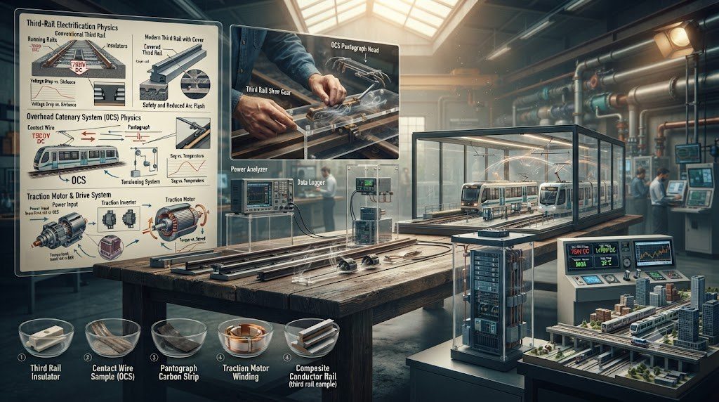
In DC-electrified metro and commuter railway networks (750V DC third-rail or 1,500V DC overhead catenary), traction substations are situated directly within or adjacent to station footprints to minimize feeder cable length and line voltage drops:
| Substation Component | Technical Electrical Rating | Operational Function in Station Complex |
|---|---|---|
| Traction Power Transformer | 11 kV / 33 kV step-down to 600V – 1,200V AC; oil-immersed or dry cast-resin. | Steps down grid utility medium voltage to traction rectifier supply level with dual phase-shifted secondaries. |
| Silicon Diode / Thyristor Rectifier | 12-pulse or 24-pulse bridge configuration; up to 4,000 kW capacity. | Converts three-phase AC into smooth DC traction voltage, minimizing harmonic ripple on third rails. |
| DC High-Speed Circuit Breaker (HSCB) | 750V / 1,500V DC; 4,000A – 6,000A continuous; 50 kA interrupt rating. | Clears catastrophic short circuits or third-rail ground faults within 10 to 15 milliseconds. |
| Regenerative Braking Energy Inverter | Bi-directional IGBT inverter or wayside supercapacitor bank. | Captures electrical energy generated by arriving braking trains and inverts it back into the AC station grid. |
| Stray Current Monitoring & Drainage | Solid-state grounding diode panels and potential-controlled drainage bonds. | Prevents DC traction return currents from leaking into station concrete rebar, stopping catastrophic electrochemical corrosion. |
Platform Screen Door (PSD) Electrical Drives and Fail-Safe Power
Modern stations increasingly deploy full-height glass Platform Screen Doors (PSD) to enhance climate control efficiency, reduce platform acoustic noise by up to 15 dBA, and eliminate track trespass or suicide hazards. The electrical operation of 40 to 60 synchronized glass sliding door leaves along a 200-meter platform requires precision engineering:
- Brushless DC (BLDC) Servo Motors: Individual door mechanisms utilize low-voltage BLDC motors controlled by digital microprocessors to execute smooth S-curve acceleration and deceleration profiles.
- Obstacle Detection Current Sensing: If an object or passenger limb obstructs a closing door leaf, motor controller current sensors detect an immediate amperage surge (> 150% rated load), instantaneously reversing door motion within 50 milliseconds.
- Emergency Manual Breakout Panels: In the event of total electrical power blackout, passengers inside a stalled train can manually push open emergency swing doors without electrical assist, requiring less than 67 N (15 lbf) of manual breakout force.
Stray Current Mitigation and Structural Rebar Cathodic Protection
In DC rail systems, the running rails serve as the return path for thousands of amperes of traction current back to the substation. Because running rails cannot be infinitely insulated from concrete trackbeds, a portion of the return current inevitably escapes into the ground as stray current. Stray current seeks out conductive station rebar, underground utility pipes, and tunnel structural steel, causing rapid electrochemical corrosion that can compromise concrete structural integrity within a decade. Station engineers install dedicated stray current collection mats beneath the track slab and monitor potential gradients using zinc reference electrodes.
Rectifier Harmonic Analysis and Twelve-Pulse vs. Twenty-Four Pulse DC Feeds
Traction Power Substations (TPSS) installed within passenger railway stations convert medium-voltage three-phase alternating current from utility power grids into direct current (DC) for traction third rails or overhead contact wires. However, the non-linear switching of high-power semiconductor rectifiers injects intense harmonic currents back into the utility grid, risking power factor penalties and equipment overheating.
To suppress harmonic distortion without requiring massive, expensive harmonic filter banks, modern rail substations deploy 12-pulse or 24-pulse rectifier configurations:
- 12-Pulse Rectification: Utilizes a specialized traction transformer with two secondary windings—one connected in Delta (Δ) and the other in Wye (Y). This introduces a 30-degree electrical phase shift between the two AC supplies feeding twin diode bridges, canceling out the 5th and 7th harmonic current orders entirely.
- 24-Pulse Rectification: Pairs two 12-pulse transformers with an additional 15-degree phase-shifting autotransformer, eliminating the 5th, 7th, 11th, and 13th harmonics and leaving Total Harmonic Distortion (THD) below 3% at the utility point of common coupling.
🚂 Regenerative Energy Recovery: Inverters vs. Supercapacitors
When dozens of trains brake simultaneously across a high-frequency metro station complex, massive electrical energy is generated. Substation engineers deploy Active Front End (AFE) bidirectional inverters that synchronize and pump this energy straight into the station’s low-voltage auxiliary AC distribution grid to power station lighting, air conditioning, and escalators. Alternatively, wayside supercapacitor banks store this energy electrostatically and discharge it in milliseconds to assist the next accelerating train, smoothing out substation peak power demand spikes by up to 35%.
Platform Screen Door (PSD) Synchronous Drive Mechanics and SIL-4 Interlocking
Full-height glass Platform Screen Door (PSD) systems installed along station platform edges are not merely architectural partitions; they are vital life-safety subsystems integrated directly into railway signaling interlockings. A typical 8-car platform incorporates 24 to 32 pairs of automated bi-parting sliding door leaves, each driven by a high-torque brushless DC (BLDC) motor coupled to a reinforced polyurethane timing belt.
To guarantee passenger safety, the electrical interlock circuit governing PSD operation adheres strictly to CENELEC SIL-4 certification:
- Closed and Locked Detection Loop: Every door leaf incorporates twin mechanical limit switches and magnetic proximity sensors wired into a fail-safe series circuit. If even a single door leaf along a 200-meter platform fails to latch securely into its mechanical lock bolt by as little as 3 mm, the series loop opens, signaling the wayside CBTC Zone Controller to drop traction power and prevent train departure.
- Anti-Entrapment Laser Curtains: In the narrow gap between the train exterior skin and the glass platform screen doors, multi-beam infrared or laser obstacle detection scanners continuously sweep the gap plane. If an object thicker than 25 mm is detected, the doors re-open automatically and an emergency alarm sounds in the central operations room.
DC Stray Current Collection Mats and Structural Corrosion Mitigation
DC rail transit systems face severe structural corrosion hazards from stray earth currents escaping from uninsulated running rails. If stray currents enter concrete platform footing rebar, the anodic electrochemical reaction oxidizes steel rebar into rust, expanding its volume by up to 600% and spalling the surrounding structural concrete. Station civil engineers install an insulated Stray Current Collection Grid—a welded mesh of reinforcement steel embedded directly beneath the trackbed slab that intercepts stray leakage currents and returns them safely through negative drainage cables back to the substation negative busbar, shielding station structural foundations from electrochemical destruction.
Station Architecture Codes, NFPA 130, and Civil Commissioning
The civil architecture, life safety systems, and mechanical infrastructure of passenger railway stations are strictly governed by international building codes and specialized transit mandates. The preeminent global standard governing passenger station life safety is NFPA 130: Standard for Fixed Guideway Transit and Passenger Rail Systems. NFPA 130 establishes prescriptive rules for station egress calculations, fire-resistant materials, emergency lighting, and tunnel smoke control ventilation. In Europe, passenger stations adhere to Technical Specifications for Interoperability (TSI PRM – Persons with Reduced Mobility) and EN 15635 for station structural integrity, while North American stations comply with the Americans with Disabilities Act (ADA) accessibility guidelines.
Commissioning a multi-level passenger railway station requires rigorous integrated systems testing:
- Full-Scale Cold Smoke & Tracer Gas Ventilation Testing: Before public opening, life-safety engineers stage full-scale cold smoke discharge tests on platform levels. Reversible axial jet fans are actuated to prove that smoke extraction shafts maintain critical airflow velocity (> 2.2 m/s), preventing deadly backlayering and ensuring tenable, smoke-free evacuation routes.
- Platform Screen Door (PSD) 100,000-Cycle Endurance Testing: Prior to revenue passenger service, all automated platform screen door leaves undergo continuous automated cycling for tens of thousands of cycles to verify mechanical belt alignment, BLDC motor thermal limits, and fail-safe laser anti-entrapment response times.
- Integrated Fire-Alarm Cause-and-Effect Matrix Validation: Engineers test emergency scenarios where simulated fire alarms simultaneously trigger: emergency escalator stopping, fare gate auto-unlock to open positions, emergency stairwell pressurization fans, public address emergency voice alarms, and traction substation emergency power trips.
Station Electromechanical Asset Management Lifecycle
A major transit station operates as an intensive continuous facility requiring structured maintenance schedules for its electromechanical infrastructure:
| Maintenance Interval | Asset Classification | Mechanical & Electrical Scope |
|---|---|---|
| Daily Pre-Operation | Life-Safety & Vertical Mobility | Operational check of all escalators, elevators, emergency exit crash bars, emergency exit lighting batteries, and public address clarity. |
| Monthly Preventative | Platform Screen Doors & Fare Gates | Cleaning of optical obstacle sensors, lubrication of PSD door roller guide rails, calibration of automated fare gate flap torque sensors. |
| Quarterly Life-Safety | Smoke Extraction & Fire Suppression | Test running of high-power reversible tunnel ventilation fans, inspection of deluge valve risers, cleaning of fire damper actuators. |
| Annual / Bi-Annual | Traction Substation & Switchgear | Thermal infrared imaging of 12-pulse rectifier transformer connections, breaker contact resistance testing, stray current collection grid potential audits. |
Technical Frequently Asked Questions (FAQ)
What is the NFPA 130 four-minute platform clearing mandate?
NFPA 130 Section 5.3.3 mandates that a station platform must be designed with sufficient vertical and horizontal egress capacity (stairwells, concourses, and passageways) to evacuate the entire design occupant load—combining waiting passengers on the platform plus a fully loaded peak-capacity train—from the platform to a point of relative safety in 4.0 minutes (240 seconds) or less. The total station must be completely evacuable to the open exterior street in 6.0 minutes. Crucially, the engineering calculation assumes that the highest-capacity escalator in the station is out of service, with remaining escalators acting as stationary stairs.
How do Platform Screen Doors (PSD) enhance passenger safety and station climate efficiency?
Platform Screen Doors provide a continuous structural glass barrier between waiting platform crowds and moving trains. They completely eliminate track trespass, accidental falls, and suicide attempts, which otherwise cause severe operational delays. From an HVAC perspective, full-height PSDs isolate air-conditioned or heated station concourses from outdoor tunnel air, cutting station HVAC thermal losses by 30% to 40% and reducing station acoustic noise by up to 15 dBA during high-speed train arrivals.
What is the Spanish Solution in railway platform geometry?
The Spanish Solution (also known as the Barcelona Solution) is an efficient platform layout where a single train track is bounded by passenger platforms on both sides: a central island platform and an outer side platform. When a train arrives, doors on both sides open simultaneously. Passengers alight onto the dedicated alighting platform while embarking passengers board from the opposite platform. By completely separating boarding and alighting passenger flows, station dwell time is reduced from 60-90 seconds down to 30-35 seconds, dramatically boosting line capacity.
What causes stray current in DC electrified railway stations and how is it mitigated?
In DC-electrified rail networks (such as 750V third rail or 1,500V catenary), running rails serve as the electrical return path back to the substation. Because rails cannot be completely insulated from concrete track slabs, a portion of the electrical current leaks into the ground as stray current. If this stray current enters reinforced concrete station foundations, the electrochemical reaction corrodes steel rebar into rust, cracking and spalling the structural concrete. To mitigate this, engineers install stray current collection steel mats beneath tracks that safely capture and return leakage current to the substation.
Solid-State DC Circuit Breakers and Fast-Acting Arc Suppression
In DC traction power substations, clearing short-circuit faults (which can exceed 50,000 amperes in fractions of a second) has traditionally relied on high-speed electromechanical circuit breakers. However, mechanical breakers require 15 to 30 milliseconds to separate physical contacts, generating massive electrical plasma arcs that erode contacts and emit acoustic blast waves. Substation manufacturers are introducing Solid-State DC Circuit Breakers (SSCBs) utilizing Silicon Carbide (SiC) or Integrated Gate-Commutated Thyristor (IGCT) semiconductor switches.
SSCBs interrupt catastrophic short circuits in under 100 microseconds—over 100 times faster than mechanical breakers. By choking fault currents before they can ramp up to destructive peak magnitudes, solid-state breakers completely eliminate destructive arc-flash events, protect third-rail contact shoes, and slash substation switchgear maintenance downtime to virtually zero.