In classical railway history, the rhythmic “clickety-clack” of steel wheels over rail joints was the signature acoustic accompaniment of train travel. In modern high-speed and heavy freight railway engineering, however, that sound has been completely engineered out of existence through the universal adoption of Continuous Welded Rail (CWR). Jointed track—where 12-to-25-meter rail sections were connected by mechanical steel fishplates and bolts—represented the single most vulnerable and labor-intensive maintenance liability in railway infrastructure.
Every mechanical rail joint creates a structural discontinuity in track stiffness, subjecting passing wheelsets to severe impact shock loads that batter rail ends, pulverize underlying ballast, and accelerate wheel bearing fatigue. By flash-butt welding or thermite welding individual steel rails into unbroken ribbons stretching for kilometers or tens of kilometers without a single joint, CWR slashes maintenance costs by over 50%, eliminates joint batter, and provides the ultra-smooth track geometry mandatory for safe 350 km/h train operations.
🚂 The Thermal Stress Constraint in Continuous Welded Rail
Because CWR rails are rigidly anchored and prevented from expanding or contracting with changing ambient temperatures, thermal fluctuations induce massive internal axial longitudinal stresses. In summer heat, longitudinal thermal expansion creates immense compressive forces capable of triggering explosive lateral track buckling (sun kinks). In freezing winter, thermal contraction generates massive tensile forces that can snap the steel rail in two.
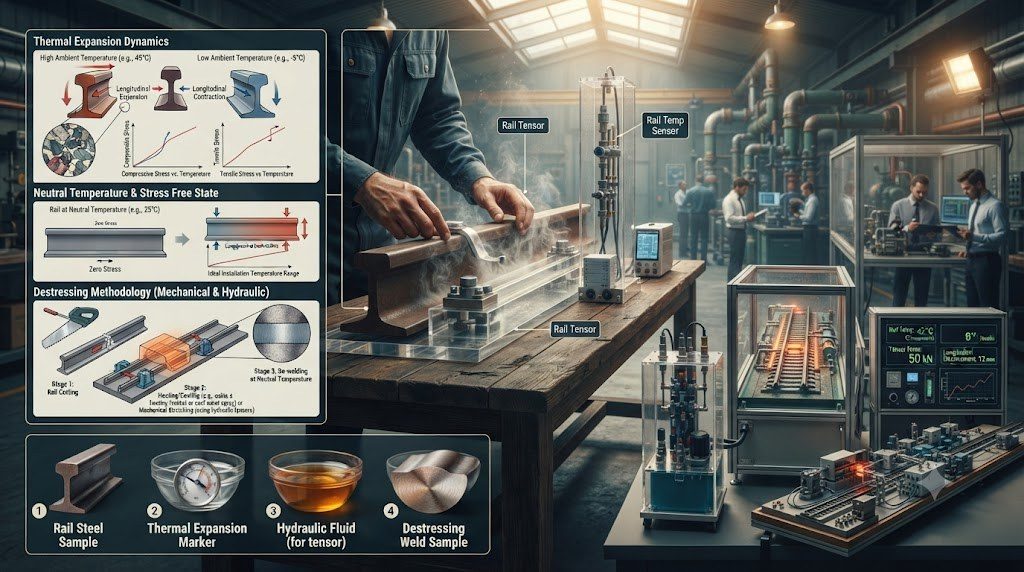
Thermal Expansion Physics and the Rail Neutral Temperature (RNT)
The longitudinal stress (sigma) induced in a fully constrained CWR rail is governed by Hooke’s Law and thermal expansion physics:
σ_{thermal} = E * α * (T_{rail} – T_{neutral}) | F_{axial} = A_{cross} * σ_{thermal}
where E is the elastic modulus of rail steel (210 GPa), alpha is the coefficient of thermal expansion (1.15 x 10⁻⁵ /°C), and A is rail cross-sectional area (approx. 77 cm² for 60 kg/m rail). A temperature swing of just 30°C away from neutral generates over 70 metric tons (700 kN) of axial compressive or tensile force inside each single rail.
| Rail Thermal State | Rail Temperature Relative to RNT | Internal Longitudinal Stress State | Primary Structural Failure Hazard |
|---|---|---|---|
| Extreme Summer Heat | T_rail > RNT + 25°C to +35°C | Massive Axial Compressive Stress (up to -150 MPa). | Track Buckling (Sun Kink): lateral track displacement causing instant derailment. |
| Optimum Neutral State | T_rail = Rail Neutral Temperature (RNT) | Zero Longitudinal Stress (σ = 0.0 MPa). | Optimal structural equilibrium; zero thermal force exerted on fasteners. |
| Moderate Operations | RNT – 15°C < T_rail < RNT + 15°C | Mild elastic tension or compression. | Safe operating envelope; track lateral resistance easily holds alignment. |
| Extreme Winter Freeze | T_rail < RNT – 30°C to -45°C | Massive Axial Tensile Stress (up to +180 MPa). | Brittle Rail Pull-Apart: transverse fracture opening wide gap in rail line. |
Hydraulic Destressing and Rail Neutral Temperature Calibration
To balance compressive buckling risks against tensile pull-apart risks, track engineers weld and anchor CWR at a mathematically calculated Rail Neutral Temperature (RNT)—typically set near the upper third of the region’s historical ambient temperature spectrum (e.g., 32°C to 38°C in temperate zones).
When installing or repairing track at lower temperatures, engineers perform hydraulic rail destressing. All fastening clips are unfastened, and the rail is elevated onto low-friction rollers. Powerful hydraulic tensor jacks grip the rail ends and physically stretch the cold steel until its elongated length matches the physical dimension it would naturally assume at the target RNT. Once fully stretched, the rail is immediately clamped down into heavy concrete sleepers and thermite-welded, locking in the pre-stressed neutral equilibrium.
Thermite Welding (Aluminothermic) vs. Mobile Flash-Butt Welding
Connecting CWR strings in the field utilizes two primary metallurgical welding processes:
- Aluminothermic (Thermite) Welding: Utilizes a highly exothermic chemical reduction reaction between iron oxide and aluminum powder: Fe₂O₃ + 2Al → Al₂O₃ + 2Fe + Heat. The reaction reaches scorching temperatures of 2,500°C within seconds inside a refractory crucible. Molten superheated steel is tapped into a preheated ceramic mold surrounding the rail gap, fusing the rail ends together. Highly portable for remote field maintenance.
- Mobile Flash-Butt Welding: Heavy rail-mounted vehicles clamp copper electrodes across the rail ends, passing hundreds of thousands of amperes across the gap. Intense electrical resistance vaporizes steel surface asperities in a shower of sparks (flashing phase). Hydraulic rams then forge the molten ends together under immense pressure (upset phase), extruding impurities and creating a forged metallurgical bond with fatigue strength nearly identical to the virgin rolled steel.
Thermal Longitudinal Stress Mechanics and Hooke’s Law in CWR
In modern high-speed and heavy-haul railway track engineering, Continuous Welded Rail (CWR) eliminates mechanical bolted rail joints over continuous spans stretching dozens or hundreds of kilometers. However, eliminating joint expansion gaps forces the steel rail to absorb all environmental temperature fluctuations as internal longitudinal axial forces. Under severe summer heat, longitudinal thermal compressive stress risks catastrophic track buckling (lateral sun kinks). In winter freezes, extreme tensile stress causes rail pulling-apart fractures.
The longitudinal axial thermal force generated inside a fully constrained continuous steel rail is governed directly by Hooke’s Law of linear thermoelasticity:
F = E · A · α · (T – TN)
where E is the Young’s modulus of elasticity of steel (207 GPa or 2.07 × 10¹¹ N/m2), A is the cross-sectional area of the rail profile (e.g., 7,686 mm2 for UIC 60 / 60E1 rail), α is the coefficient of thermal linear expansion for rail steel (1.15 × 10⁻⁵ /°C), T is the actual real-time steel rail temperature, and TN is the engineered Rail Neutral Temperature (RNT), also known as the stress-free temperature.
🚂 The 1,000-Kilonewton Buckling Threat
For a standard UIC 60 rail section, every single degree Celsius deviation from the neutral temperature induces approximately 18.3 kilonewtons of internal axial force per rail. If rail temperature rises 35°C above neutral on a blazing summer afternoon, the rail experiences over 640 kN of axial compressive force per rail—exceeding 1.28 meganewtons (130 metric tons) of compressive force across the track pair! Without massive ballast shoulder lateral resistance, the track structure buckles sideways instantly under passing train vibrations.
Hydraulic Tensor Destressing and Flash-Butt Welding Workflows
To safely set the Rail Neutral Temperature within the optimal regulatory target band (typically 27°C to 35°C depending on regional climate), track engineering crews execute standardized hydraulic destressing procedures:
- Unclipping and Roller Placement: Elastic rail fastening clips (such as Pandrol e-Clips or Fastclips) are removed over an anchoring length of 1,000 meters. The rails are jacked onto low-friction roller bearings to allow free longitudinal expansion.
- Vibratory Agitation: Crews run motorized vibrating sleds or strike the rail web with rubber mallets to release residual friction trapped at tie plates.
- Hydraulic Tensioning (Tensor Pulling): Heavy hydraulic rail pullers clamp onto the rail ends, applying calculated tension forces (often 300 to 500 kN) to physically stretch the rail to the precise mathematical length corresponding to the target RNT.
- Permanent Fusion Welding: While held under hydraulic tension, the gap is welded shut using mobile automated Flash-Butt Welding (FBW) machines or high-purity aluminothermic (thermite) charge crucible pours, followed by rapid clip re-torquing before releasing tension.
Lateral Track Resistance and Ballast Shoulder Compaction
The sole physical force preventing a heavily compressed CWR track from buckling laterally into a sun kink is the lateral ballast resistance provided by the ballast bed. Track engineering standards require crushed angular granite ballast compacted with deep shoulder widths (minimum 350 to 450 mm beyond sleeper ends) and elevated ballast heaps. Dynamic track stabilizers vibrate and consolidate the ballast matrix immediately following tamping operations, restoring lateral resistance above 12 kN/m of track length.
Civil Engineering Standards, AREMA, and Permanent Way Commissioning
Track civil engineering, subgrade stabilization, and permanent way maintenance are governed by comprehensive international technical frameworks. In North America, the American Railway Engineering and Maintenance-of-Way Association (AREMA) Manual for Railway Engineering establishes prescriptive civil standards for rail steel chemistry, ballast gradation (AREMA No. 4 and 4A), sleeper prestressed concrete design, and turnout geometric tolerances. In Europe, the European Committee for Standardization (CEN) enforces EN 13230 for concrete sleepers, EN 13674 for Vignole railway rails, and EN 13848 for track geometry quality standards, validated under Technical Specifications for Interoperability (TSI Infrastructure).
Before a newly constructed or rehabilitated track corridor can be certified for revenue traffic, civil engineering authorities execute comprehensive commissioning protocols:
- Laser Alignment and Dynamic Gauge Proving: High-speed optical track measurement vehicles survey the entire corridor at line speed, recording cross-level cant, gauge deviations, and vertical profile irregularities to verify compliance with EN 13848-5 Quality Class A standards.
- Dynamic Ballast Consolidation Verification: Dynamic track stabilizers apply horizontal lateral vibrations and vertical static loads across the trackbed. Penetrometer compaction testing confirms that ballast lateral shoulder resistance exceeds 12 to 14 kN/m before lifting temporary slow speed restrictions.
- Non-Destructive Weld Inspection (NDT): Every single flash-butt and thermite field weld is subjected to 100% ultrasonic flaw testing per EN 14730 and magnetic particle inspection (MPI) to detect internal micro-voids, lack of fusion, or transverse shrinkage cracks.
Track Asset Lifecycle Management and Ultrasonic Inspection Regimes
Modern railway permanent way infrastructure is maintained under continuous predictive lifecycle asset management schedules:
| Maintenance Interval | Inspection Classification | Civil Engineering Intervention |
|---|---|---|
| Daily Track Patrol | Visual & Ultrasonic Hi-Rail Inspection | Visual inspection of rail fastenings, switch point gaps, track lubricator levels, and railhead surface defects. |
| Quarterly / Monthly | Autonomous Track Geometry Recording | Dynamic measurement car runs recording Track Quality Index (TQI); automated flagging of localized twist or alignment defects. |
| Semi-Annual (Winter/Summer) | CWR Stress-Free Neutral Temperature Audit | Measurement of rail creep markers, tensor destressing of track sections, and verification of anchor lengths before extreme seasonal temperatures. |
| Every 5 to 7 Years / 150 MGT | Ballast Undercutting & Screening | Heavy undercutting machines excavate fouled, pulverized ballast, screen out fine silt and clay aggregates, and inject fresh crushed granite stone. |
Technical Frequently Asked Questions (FAQ)
What causes rail track buckling in extreme summer heat and how is it prevented?
Continuous Welded Rail (CWR) expands under summer heat. Because the rail is continuously welded without expansion gaps, the thermal expansion creates immense internal longitudinal compressive forces (exceeding 600 kN per rail). If the lateral resistance provided by the crushed stone ballast shoulder is insufficient, or if track alignment is slightly irregular, the track will violently buckle sideways in an instant (a ‘sun kink’), causing severe derailments. Buckling is prevented by prestressing rails to an engineered Rail Neutral Temperature (RNT, typically 28°C to 35°C) during installation, maintaining wide compacted ballast shoulders (≥ 400 mm), and deploying continuous thermal sensors along vulnerable track sections.
What is the difference between ballasted track and concrete slab track?
Ballasted track places wooden or prestressed concrete sleepers upon a thick bed of crushed angular granite stone (ballast). It is economical to build, offers excellent drainage, and is easily re-aligned using automated tamping machines, but requires frequent, labor-intensive maintenance throughout its life. Non-ballasted slab track (such as Rheda 2000) fixes rails directly to reinforced concrete pavement slabs. Slab track has high initial capital construction costs but requires virtually zero alignment maintenance for over 40 years, retains millimeter-perfect geometry at speeds exceeding 300 km/h, and slashes tunnel excavation cross-sections by eliminating ballast cushion thickness.
Why is rail grinding performed regularly on heavy-haul and high-speed railways?
Passing train wheels exert cyclic dynamic stresses exceeding 1,500 MPa at the microscopic wheel-rail contact patch, inducing Rolling Contact Fatigue (RCF) in the rail steel surface. This leads to micro-cracks (head checks) that can propagate downward into catastrophic transverse rail fractures. Rail grinding trains deploy dozens of rotating abrasive grinding stones or rotary milling cutters that shave away 0.2 to 1.0 mm of fatigued surface steel, removing micro-fissures and restoring the engineered transverse railhead profile to minimize wheel wear and hunting oscillations.
How do railway switch point machines verify that turnout points are securely locked?
Modern point machines (such as the Siemens S700K) utilize independent internal mechanical lock rods and electrical detector rods. After the motor throws the switch blade against the stationary stock rail, the lock rod physically drops into place, mechanically locking the switch blade so that passing trains cannot force it open. Simultaneously, microswitches verify that the gap between the blade and stock rail is strictly less than 2.0 to 3.0 mm. If a ballast stone or ice prevents the blade from locking flush, the detection circuit breaks, preventing the signaling system from displaying a proceed aspect.