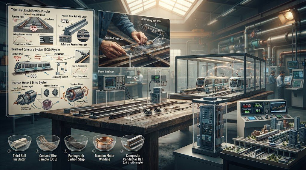
Where traffic density, passenger volume, and environmental mandates justify high capital infrastructure investment, electric locomotives represent the pinnacle of rail transport efficiency, raw power density, and environmental sustainability. By drawing continuous electrical energy from an external stationary grid via overhead catenary lines (OHE) or third-rail conductors, an electric locomotive eliminates the massive weight, volume, and fuel consumption of an on-board diesel prime mover, dedicating nearly 100% of its physical chassis to high-output traction machinery.
Operating at power ratings from 6,000 to over 12,000 horsepower (9,000 kW) in a single compact locomotive unit, electric locomotives achieve acceleration curves, sustained high speeds, and mountain-grade climbing capabilities that leave diesel units far behind. However, realizing this immense power requires mastering high-voltage overhead catenary pantograph dynamics, electromagnetic interference (EMI) suppression, and regenerative braking power return into the national electrical grid.
🚂 The Regenerative Braking Grid Feedback Miracle
Unlike diesel locomotives that dissipate braking kinetic energy as waste heat through roof resistors, electric locomotives utilize full regenerative braking. During deceleration or mountain descents, traction inverters reverse power flow, converting train momentum into clean, synchronized alternating current that is injected directly back into the overhead catenary line to power adjacent ascending trains or feed the national grid.
Overhead Electrification Standards: AC vs. DC Electrification Systems
Global railway electrification systems are standardized across distinct voltage and frequency regimes:
| Electrification System | Nominal Voltage & Frequency | Substation Spacing (km) | Primary Rolling Stock Application & Constraints |
|---|---|---|---|
| 25 kV AC (Standard Global) | 25,000 Volts AC @ 50 Hz or 60 Hz | 40 – 60 km apart | High-Speed Rail (TGV, Shinkansen) and modern freight mainlines; minimal current line loss. |
| 15 kV AC (Central Europe) | 15,000 Volts AC @ 16.7 Hz (one-third grid) | 25 – 40 km apart | Germany, Austria, Switzerland, Sweden; legacy low-frequency AC traction networks. |
| 3 kV DC Electrification | 3,000 Volts DC steady potential | 15 – 25 km apart | Italy, Spain, Poland, South Africa; requires heavy copper catenary and frequent substations. |
| 1.5 kV DC Electrification | 1,500 Volts DC steady potential | 8 – 15 km apart | Urban metro corridors and legacy French mainlines; high current requires thick dual contact wires. |
| 750V DC Third Rail | 750 Volts DC bottom/top contact shoe | 2 – 5 km apart | Urban transit metros and London commuter rail; severe safety hazard at ground level. |
Pantograph Aerodynamics and Catenary Wave Propagation Dynamics
At high speeds (exceeding 250 to 350 km/h), collecting hundreds of amperes of current through a moving contact wire is an extraordinary mechanical challenge. The pantograph—a roof-mounted articulating scissor or single-arm pneumatic linkage—must maintain constant, unyielding upward contact pressure (typically 70 to 120 Newtons) against the suspended copper catenary wire.
When the pantograph pushes against the contact wire, it generates a transverse mechanical wave that travels along the catenary wire ahead of the train. The velocity of this wave is governed by wire mechanical tension and linear mass density:
c_{wave} = √( T_{tension} / ρ_{linear} )
If train speed approaches or exceeds this mechanical wave speed (the critical Doppler limit), the wire oscillates violently, the pantograph loses physical contact, and continuous high-voltage electrical arcing vaporizes the carbon contact strip and severing the catenary. High-speed rail catenary lines are tensioned up to 20 to 30 kiloNewtons using automated hydraulic or counterweight tensioning devices to keep wire wave speeds safely above 450 km/h.
On-Board Traction Converters: Four-Quadrant Transformers and Inverters
Inside the locomotive machine room, high-voltage 25 kV AC entering from the pantograph passes through a roof vacuum circuit breaker into the primary winding of a massive underfloor traction transformer. Multiple secondary windings supply Four-Quadrant Active PWM Rectifiers utilizing water-cooled Silicon Carbide (SiC) or IGBT switches.
These four-quadrant converters maintain a unity power factor on the overhead catenary while maintaining a stable intermediate DC link. Variable-frequency motor inverters then convert this DC bus into precision three-phase AC to drive high-torque traction motors, achieving total electrical-to-mechanical conversion efficiencies exceeding 92% across all speed ranges.
Pantograph Dynamic Aerodynamics and Wave Propagation Mechanics
At high operational velocities (250 to 350 km/h), the physical interaction between the roof-mounted pantograph and the overhead contact wire transitions from a quasi-static mechanical contact problem into a complex aero-elastic wave dynamics challenge. When a pantograph slides along a tensioned copper contact wire, it imparts an upward mechanical lifting force (typically 70 to 120 N). This displacement generates mechanical transverse transverse waves that propagate along the overhead wire both ahead of and behind the moving train.
The speed at which transverse mechanical waves propagate along the overhead contact wire is governed by the classical string wave equation:
c = √(T / μ)
where c is the critical wave propagation velocity, T is the mechanical tensile tension applied to the wire by lineside tensioning counterweights (typically 20 to 35 kN), and μ is the mass per unit length of the contact wire (typically 1.0 to 1.35 kg/m). In high-speed railway engineering, the train’s maximum operating speed must never exceed 70% to 75% of the contact wire wave velocity (v ≤ 0.70 c). Approaching or exceeding the wave velocity causes the pantograph to catch up with its own reflected displacement wave, inducing violent contact bounce, severe electrical arcing, wire dewirement, and catastrophic pantograph destruction.
🚂 Active Aerodynamic Aerofoils and Closed-Loop Uplift Control
Modern high-speed pantographs—such as the Faiveley CX or Schunk WBL 85—incorporate micro-aerodynamic winglets and servo-actuated pneumatic cylinders on the pantograph collector head. At cruising velocities above 300 km/h, computer-controlled pneumatic regulators actively adjust contact force in real time, compensating for turbulent tunnel pressure waves and aerodynamic vehicle bow-wave uplifts to maintain steady contact pressure within ±5% tolerance.
Transformer Core Saturation and Four-Quadrant Converter Operation
Electric locomotives operating on 25 kV AC 50/60 Hz or 15 kV AC 16.7 Hz overhead catenaries utilize an underfloor-mounted main traction transformer. Transformer design for rolling stock demands extraordinary power density, packing 6,000 to 9,000 kVA of electrical transformation capacity into a low-profile tank filled with synthetic ester dielectric fluid with high flash points (> 300°C) for fire safety in passenger tunnels.
Downstream of the main transformer secondary windings, modern locomotives deploy Four-Quadrant Inverter Converters (4QC). Utilizing pulse-width modulated IGBT or Silicon Carbide (SiC) switches, the 4QC performs two critical functions:
- Unity Power Factor Control: It conditions input AC current to remain precisely in-phase with the catenary voltage waveform, maintaining a displacement power factor (cos φ) above 0.98 and minimizing reactive power consumption from the electrical utility grid.
- Bidirectional Power Flow (Regeneration): When the locomotive applies service brakes, the 4QC inverts DC energy generated by traction motors back into clean, synchronized AC current, pumping high-voltage electricity back into the overhead catenary for nearby accelerating trains to consume.
Phase Separation Neutral Sections and Auto-Switching Electronics
Commercial high-voltage AC rail catenaries are energized from distinct phases of the national three-phase electrical transmission grid to maintain balanced three-phase utility loading. Consequently, every 25 to 50 kilometers along the route, a short segment of dead, unpowered trackway known as a Phase Neutral Section is installed to prevent adjacent electrical phases from short-circuiting together.
Traversing a neutral section requires automated onboard management: trackside magnetic balises signal the locomotive’s onboard computer, which commands the main Vacuum Circuit Breaker (VCB) to open under zero load in under 20 milliseconds, cuts traction inverter output, glides through the 50-meter neutral dead section under vehicle inertia, and automatically recloses the VCB upon sensing the new phase voltage, restoring full traction in under 200 milliseconds without driver intervention.
International Catenary Standards, TSI Energy, and Commissioning
Electric railway traction and overhead contact line (OCL) systems are governed internationally by rigorous engineering standards that ensure cross-border interoperability and high-speed mechanical stability. In Europe and global high-speed corridors, CENELEC EN 50119 specifies requirements for overhead contact line design and construction, while EN 50367 defines the dynamic interaction rules between pantographs and overhead lines. European railway corridors comply strictly with the Technical Specifications for Interoperability (TSI Energy), which mandate standard catenary heights (5.0 to 5.5 meters above top of rail), contact wire lateral stagger (zigzag amplitude of ±200 to ±300 mm to ensure even carbon strip wear), and permissible contact force bands (typically 60 to 120 N for high-speed operation).
Commissioning an electrified high-speed line requires intensive dynamic instrumented validation testing:
- Instrumented Pantograph Test Runs: Dedicated measurement trainsets equipped with fiber-optic strain gauges, high-speed optical cameras, and load cells on the pantograph collector head traverse the newly electrified corridor at incrementally increasing speeds (from 160 km/h up to 350+ km/h). Real-time telemetry logs contact wire uplift, vertical contact forces, and electrical contact loss arcing percentages per EN 50317 standards.
- Substation Short-Circuit Staging: High-voltage substation commissioning engineers stage controlled bolted short-circuit tests at the furthest extremity of each feeding section to verify that solid-state protection relays detect phase-to-ground faults and trip high-speed vacuum circuit breakers within 30 to 45 milliseconds.
- Catenary Dynamic Resonance Profiling: Engineers verify that the mechanical natural resonant frequencies of the tensioned catenary spans do not coincide with the pantograph passing frequencies at maximum operating speeds, preventing destructive harmonic standing waves.
Preventative Catenary and Pantograph Maintenance Protocols
Because overhead catenary failure causes immediate line shutdowns and strandings, electric rail systems execute proactive preventative maintenance schedules:
| Inspection Frequency | Asset Monitored | Maintenance Technology & Procedure |
|---|---|---|
| Daily Pre-Departure | Pantograph Carbon Collector Strips | Visual inspection for cracks, chipping, or deep grooving; ultrasonic thickness check (> 5mm carbon remaining). |
| Monthly High-Speed Scan | Overhead Contact Wire Thickness | Autonomous optical laser scanning cars measuring residual wire diameter at line speed; flags localized mechanical wear spots. |
| Biannual Mechanical Check | Catenary Tensioning Weights & Pulleys | Inspection of lineside tension wheel pulleys, stainless steel balance ropes, and counterweights to guarantee constant mechanical tension across seasonal temperature swings. |
| Every 3 to 5 Years | Insulator Cleaning & Thermal Imaging | Infrared thermographic surveys from helicopter or drone to detect hot spots on catenary splices, combined with high-pressure washing of ceramic and silicone composite insulators to prevent flashovers. |
Technical Frequently Asked Questions (FAQ)
Why is overhead catenary wire installed in a zigzag (staggered) alignment instead of a straight line?
If the overhead contact wire were strung in a perfectly straight line along the center of the track, the copper wire would rub continuously against the exact same spot on the locomotive pantograph’s carbon collector strip. Within a few hours of operation, the wire would saw a deep, destructive groove into the carbon strip, causing the collector head to jam, snap the overhead wire, and tear the pantograph off the roof. By staggering the wire laterally left and right across mast supports (±200 to 300 mm from track center), the wire slides back and forth across the entire width of the carbon collector strip, distributing friction and ensuring completely uniform wear.
What happens when an electric train crosses a phase neutral section at high speed?
Phase neutral sections separate different sections of the overhead catenary fed by different electrical utility grid phases to prevent short circuits. When an electric train approaches a neutral section, trackside transponders (Eurobalises) signal the onboard computer. The locomotive automatically cuts traction power, opens its high-voltage vacuum circuit breaker (VCB) under zero electrical current, lowers pantograph current collection, and coasts through the 50-meter unpowered neutral section under vehicle momentum. Once past the section, the computer detects the new phase voltage and closes the VCB, smoothly ramping traction power back up in fractions of a second.
Why do electric locomotives achieve higher energy efficiency than diesel locomotives?
Electric locomotives draw electrical power directly from centralized utility power grids, which produce electricity from high-efficiency combined-cycle gas, nuclear, hydro, and renewable wind/solar installations operating at 50% to 90% thermal efficiency. Furthermore, electric locomotives do not have to haul the immense dead weight of heavy diesel engines, fuel tanks, cooling radiators, and alternators. Finally, electric locomotives utilize regenerative braking to feed recovered kinetic energy directly back into the overhead catenary for adjacent trains to use, yielding an overall wheel-to-wire energy efficiency of over 80% compared to 30% to 35% for diesel-electric engines.
What materials are used for pantograph collector strips and why?
Pantograph collector strips are manufactured from specialized synthetic metallized carbon graphite composites or sintered copper-carbon mixtures. Carbon graphite possesses a unique combination of engineering properties: it provides excellent electrical conductivity while exhibiting natural self-lubricating characteristics that dramatically reduce mechanical friction against the hard-drawn copper contact wire. Crucially, carbon is softer than the copper catenary wire, ensuring that the inexpensive, easily replaceable pantograph collector strip wears out rather than the costly overhead wire.